| 1. Scope of the coverage: |
| This specification is pertinent to the application of cement
resistors [designated as (RGW), (RGF)]. |
| 2 .Temperature range of the application: |
| -55℃ ~ +155℃。 |
| 3. Type: |
| Two types of cement resistors are available : wire wound
cement resistor (RGW) and metal oxide |
| film cement resistor (RGF) |
| 4.Marking and illustration: ref. To Fig.1 |
 |
| |
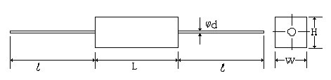
| 5.Dimension, voltage, resistance
range: listed in the following Table (Fig.1 - Fig.6)
Unit: mm |
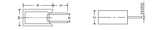
| 5.1 Z Type |
 |
| Rated
Power
(W) |
Type |
Resistance
Range(Ω) |
Highest Working
(V) |
Highest Overload
(V) |
Dimension (ref. to Fig.1) |
| J ( ±5%) |
W |
L |
HI |
H2 |
P |
| 3 |
RGW |
0.1~100Ω |
|
|
10±1 |
25±1.5 |
10±1 |
|
9.5±1.5 |
| RGF |
101Ω~39KΩ |
350 |
1000 |
| 5 |
RGW |
0.1~100Ω |
|
|
10±1 |
28±1.5 |
10±1 |
15±1.5 |
| RGF |
101Ω~50KΩ |
350 |
1000 |
| 7 |
RGW |
0.1~100Ω |
|
|
10±1 |
36±1.5 |
10±1 |
20±1.5 |
| RGF |
101Ω~100KΩ |
500 |
1500 |
| 10 |
RGW |
0.1~100Ω |
|
|
10±1 |
48±1.5 |
10±1 |
32±1.5 |
| RGF |
101Ω~100KΩ |
750 |
1500 |
| 15 |
RGW |
0.1~100Ω |
|
|
12.5±1 |
48±1.5 |
12±1 |
32±1.5 |
| RGF |
101Ω~100KΩ |
1000 |
1500 |
| 20~25 |
RGW |
0.1~100Ω |
|
|
15±1 |
60±1.5 |
13±1 |
42±1.5 |
| RGF |
101Ω~100KΩ |
1000 |
1500 |
|
| |
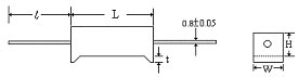
| 5.2 P Type (Fig.2 Unit: mm) |
| |
| Rated Power |
W |
H |
L |
dφ |
ι |
| 2W |
7 ±1.0 |
7 ±1.0 |
18 ±1.5 |
0.8 ±0.05 |
23 ±3 |
| 3W |
8 ±1.0 |
8 ±1.0 |
22 ±1.5 |
0.8 ±0.05 |
35 ±3 |
| 5W |
10 ±1.0 |
9 ±1.0 |
22 ±1.5 |
0.8 ±0.05 |
35 ±3 |
| 7W |
10 ±1.0 |
9 ±1.0 |
35 ±1.5 |
0.8 ±0.05 |
35 ±3 |
| 10W |
10 ±1.0 |
9 ±1.0 |
48 ±1.5 |
0.8 ±0.05 |
35 ±3 |
| 15W |
12.5 ±1.0 |
11.5 ±1.0 |
48 ±1.5 |
0.8 ±0.05 |
35 ±3 |
| 20W~25W |
14 ±1.0 |
13.5 ±1.0 |
60 ±1.5 |
0.8 ±0.05 |
35 ±3 |
|
| |
| 5.3 M Type (Fig.3 Unit: mm) |
 |
| Rated Power |
H |
W |
S |
dφ |
P |
| 2W |
20 ±1.5 |
11 ±1.0 |
7 ±1.0 |
0.8 ±0.05 |
|
| 3W |
25 ±1.5 |
12 ±1.0 |
8 ±1.0 |
0.8 ±0.05 |
|
| 5W |
25 ±1.5 |
13 ±1.0 |
9 ±1.0 |
0.8 ±0.05 |
|
| 7W |
39 ±1.5 |
13 ±1.0 |
9 ±1.0 |
0.8 ±0.05 |
|
| 10W |
51 ±1.5 |
13 ±1.0 |
9 ±1.0 |
0.8 ±0.05 |
|
| 15W |
35 ±1.5 |
16 ±1.0 |
12 ±1.0 |
0.8 ±0.05 |
|
|
| |
| 5.4 T Type (Fig.4 Unit: mm) |
| |
| Rated Power |
W |
H |
L |
t |
dφ |
| 5W |
10 ±1.0 |
9 ±1.0 |
22 ±1.5 |
1.5 ±0.5 |
0.8 ±0.05 |
| 7W |
10 ±1.0 |
9 ±1.0 |
35 ±1.5 |
3.0 ±0.5 |
0.8 ±0.05 |
| 10W |
10 ±1.0 |
9 ±1.0 |
48 ±1.5 |
3.0 ±0.5 |
0.8 ±0.05 |
|
| |
| 5.5 S Type (Fig.5 Unit: mm) |
 |
| Rated Power |
L |
H |
HI |
K |
h |
| 7W |
46 ±1.5 |
28 ±0.5 |
7.0 ±0.5 |
6.5 ±0.5 |
4.0±0.3 |
| 10W |
60 ±1.5 |
28 ±0.5 |
7.0 ±0.5 |
20 ±0.5 |
4.0±0.3 |
|
| |
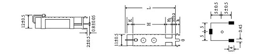
| 5.6 H Type (Fig.6 Unit: mm) |
 |
| |
W |
H |
L |
P |
HI |
D |
P1 |
P2 |
| 10W |
10.0±1 |
10.0±1 |
48.0±1.5 |
32.0±1 |
21.0±1 |
5.0±0.5 |
2.5±0.2 |
1.7±0.2 |
| 15W |
12.5±1 |
11.5±1 |
48.0±1.5 |
32.0±1 |
21.0±1 |
5.0±0.5 |
2.5±0.2 |
1.7±0.2 |
| 20W |
14.5±1 |
13.5±1 |
60.0±1.5 |
42.0±1 |
24.0±1 |
6.0±0.5 |
3.0±0.2 |
2.5±0.2 |
| 30W |
19.0±1 |
19.0±1 |
75.0±1.5 |
55.0±1 |
31.0±1 |
7.5±0.5 |
. |
. |
| 40W |
19.0±1 |
19.0±1 |
90.0±1.5 |
67.0±1 |
31.0±1 |
7.5±0.5 |
. |
. |
|
| |
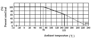
| 6. Characteristics of electrical performance |
| 6.1 Rated power |
| The rated power indicates the maximum power the resistor
can endure continuously when the |
| ambient temperature is equal to or lower than 70℃. When
the ambient temperature is higher than |
| 70℃, the rated power of the resistor is determined by the
derating curve described in the following |
| figure. |
|
| 6.2 Rated voltage |
| The rated voltage of a resistor is either a continuous
DC voltage or an AC rms voltage which can be |
| calculated by the following formula. If the calculated
rated voltage is higher than the highest |
| working voltage then the highest working voltage should
be used as the rated voltage. |
 P: Rated power(W), R: Nominal resistance(Ω),
E: Rated voltage(V) P: Rated power(W), R: Nominal resistance(Ω),
E: Rated voltage(V) |
| |
| 6.3 Insulation resistance (Ref. JIS C5202 5.6) |
| Equipment: Insulation resistance tester |
| The body of the resistor is wrapped around by the aluminum
foil without extending beyond the |
| resistor body. Clap one electrode on the aluminum foil
and the other electrode on the lead wire. |
| Apply 500V from the tester for 1 min. and the measured
resistance value should be larger than |
| 100MW. |
| |
| 6.4 Dielectric strength (Ref. JIS C5202 5.7) |
| Equipment: Dielectric strength tester |
| The body of the resistor is wrapped around by the aluminum
foil without extending beyond the |
| resistor body. Clap one electrode on the aluminum foil
and the other electrode on the lead wire. |
| Apply 1,000V from the tester to the resistor for 1 min..
No flash-over, burning or breakdown should |
| be observed. |
| |
| 6.5 Short time overload (SOL) (Ref. JIS C5202 5.5) |
| Equipment: S.O.L. tester. |
Apply voltage of  to the resistor for 5 sec., After the test, stabilize the
resistor at room
to the resistor for 5 sec., After the test, stabilize the
resistor at room |
| temperature for 30 min. then measure its resistance. Compare
the resistance before and after the |
| test. The acceptable change of the resistance is: ±(2%+0.1Ω).
The highest applied overload |
| voltage is listed in Table-1. |
| |
| 7. Environmental tests |
| 7.1 Load life test (Endurance with rated load) (Ref. JIS
C5202 7.10) |
| Equipment: High temperature chamber and DC power supply |
| The resistors are put in a fixture where no interference
will be allowed. Put the fixture in a 70±3℃ |
| chamber and apply rated voltage with a cycle of 90 min.
ON and 30 min. OFF for 1000+48-0 hours. |
| After 240, 480, 720 and 1,000 hours, the resistors are
taken out and stabilize at room temperature |
| for 30 min. and then the resistance is measured. Upon each
step of resistance measurement, the |
| change of the resistance should not exceed ±(5%+0.1Ω) and
the appearance should show no |
| remarkable abnormality and legibility of marking. |
| |
| 7.2 Resistance to damp heat (Ref. To JIS C5202 7.2) |
| Equipment: Constant temperature and humidity chamber |
| The resistors are put in a 40±2℃ chamber with RH=90~95%
for 56 days. After the test, take the |
| resistors out and stabilize in room temperature for 1 -
4 hour. Measure the resistance. The |
| acceptable change of resistance should not exceed ±( 3%+0.1Ω)
and the appearance should |
| show no remarkable abnormality and legibility of marking. |
| |
| 7.3 Temperature coefficient (TCR) (Ref. JIS C5202 5.2) |
| Equipment: High temperature chamber |
| Measure the resistance at room temperature. Put the resistor
in a chamber with the temperature of |
| RT+100℃ for 30 - 45 min. to stabilize. Measure the resistance
again. Compare the resistance at |
| these two temperatures with the following equation and
the acceptable value is: |
| R≦1Ω:±600 PPM/℃. or R>1Ω:±350 PPM/℃. |
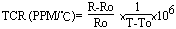 |
| R = Resistance at T T = RT + 100℃ Ro = Resistance at To
To =room temperature |
| |
| 7.4 Resistance to heat (Ref. JIS C5202 7.2) |
| Equipment: High temperature chamber |
| Measure the resistance at room temperature. Put the resistors
to 155℃ chamber for 1,000 hours. |
| Take resistors out and stabilize at room temperature for
1 hour. Measure the resistance value. The |
| change of the resistance before and after the test should
be less than ±(5%+0.1Ω). The |
| appearance should show no remarkable abnormality and legibility
of marking. |
| |
| 7.5 Temperature cycling (Ref. JIS C5202 7.4) |
| Equipment: High temperature chamber, low temperature chamber |
| Measure the resistance before the test. Put the resistor
to -55℃ chamber for 30 min. then take it |
| out at room temperature for 2 to 3 min.. Put the resistor
to +155 ℃chamber for 30 min. then take it |
| out at room temperature for 2 to 3 min. This completes
a cycle. Repeat the cycle 5 times. Put |
| resistors at room temperature for 90 min. and then measure
the resistance. Compare the |
| resistance before and after test. The acceptable change
of resistance is ±(1%+0.05Ω). The |
| appearance should show no remarkable abnormality and legibility
of marking. |
| |
| 8.Mechanical performance |
| 8.1 Resistance to soldering heat (Ref. JIS C5202 6.4) |
| Equipment: Solder bath |
| Measure the resistance before the test. Immerse part of
the lead wire which is 4±0.8mm away from |
| the body to the flux for 5 - 10 sec. Take the resistor
out and immerse resistors in the solder bath of |
| 350±10℃ for 3.5±0.5 sec.. Stabilize at room temperature
for 1 hour and then measure the |
| resistance value. Compare the resistance values before
and after the test, The acceptable change |
| is ±(1%+0.05Ω) |
| |
| 8.2 Solderability (Ref. JIS C5202 6.5) |
| Equipment: Solder bath |
| Immerse part of the lead wire which is 4±0.8mm away from
the body to the flux for 5 - 10 sec. Take |
| the resistor out and immerse resistors in the
solder bath of 245±5℃ for 2 sec.. Take the resistor |
| out and inspect the lead wire visually. The acceptable
level is the coverage of the new solder to be |
| 95%. The composition of the solder bath is 99.7% tin and
0.3% Cu. |
| |
| 8.3 Robustness of terminals (Ref. JIS C5202 6.1) |
| 8.3.1 Tensile strength of termination |
| Equipment: Weight gauge |
| Fixed the resistor and apply gradually along the terminal
4Kg of force for 30 sec., The lead wire |
| should not break or detached from the resistor and the
change of the resistance should be less |
| than ±(1%+0.05Ω). |
| |