| 1. Scope of the coverage: |
| This specification is pertinent to the application of wire
wound resistors (designated as RW). |
| 2 .Temperature range of the application: |
| -40℃ ~ +155℃。 |
| 3. Type: |
| Two types of wire wound resistors are available:
one is normal size and the other one is small |
| size. These two types are distinguished by the color of
the coating resin. The color of the resin for |
| the normal size is gray and that for the small size is
pinkish red. |
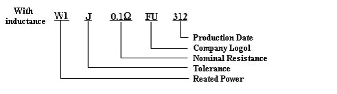
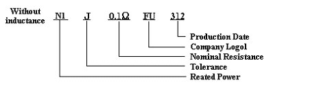
| 4.Marking and illustration: ref. To Fig.1, Fig.2: |
| Two types of designation are used to distinguish wire wound
resistors with or without inductance. |
| The one with inductance is: (RWU/S) and the one without
(low) inductance is : (NWU/S). |
| With inductance---------- >1/2W、1W、2W、3W、S1W、S2W、S3W、S5W
(Fig.1) |
| Without inductance ------------>1/2W、1W、2W、3W、S1W、S2W、S3W、S5W
(Fig.2) |
| (without inductance means low inductance or inductance
is <1μH) |
 |
 |
| |
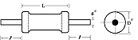
| 5.Dimension, voltage, resistance range: listed
in the following Table |
| Rated
Power
(W) |
Type |
Resistance Range
(Ω) |
 2 2 |
| J ( ±5%) |
L |
Dψ |
ι |
dψ |
| 1/4 |
Normal |
0.1~150 |
6±0.3 |
2.4±0.1 |
28±2 |
0.6±0.05 |
| 1/2 |
Small |
0.1~150 |
6±0.3 |
2.4±0.1 |
28±2 |
0.6±0.05 |
| Normal |
0.1~150 |
9±0.5 |
3.0±0.5 |
30±3 |
0.6±0.05 |
| 1
|
Small |
0.1~330 |
9±0.5 |
3.0±0.5 |
30±3 |
0.8±0.05 |
| Normal |
0.1~330 |
|
4.0±0.5 |
38±3 |
0.8±0.05 |
| 2 |
Small |
0.1~680 |
|
4.0±0.5 |
38±3 |
0.8±0.05 |
| Normal |
0.1~680 |
|
5.5±0.5 |
38±3 |
0.8±0.05 |
| 3 |
Small |
0.1~1K |
|
5.5±0.5 |
38±3 |
0.8±0.05 |
| Normal |
0.1~1K |
|
8.5±0.5 |
38±3 |
0.8±0.05 |
| 5 |
Small |
0.1~1K |
|
8.5±0.5 |
38±3 |
0.8±0.05 |
| 7 |
Small |
0.1~15K |
|
8.5±0.5 |
38±3 |
0.8±0.05 |
| 10 |
Small |
0.1~27K |
8 (MAX) |
44 (MAX) |
38±3 |
0.8±0.05 |
|
| P/S:7W、10W is for Philips specification only. |
| |
| 6.Coating |
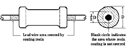 |
| 6.1 The body of the resistor is covered by nonflammable
silicon resin. |
| 6.2 The maximum length of the lead wire covered by the
resin is 2mm. |
| 6.3 The maximum area of the end cap which is not covered
by the resin is half of the diameter of |
| 6.3 the cap. |
| 6.4 The status of coating condition described by 6.2 and
6.3 are acceptable. |
| |
| 7.Characteristics of electrical performance |
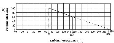
| 7.1 Rated power |
| The rated power indicates the maximum power the resistor
can endure continuously when the |
| ambient temperature is equal to or lower than 70℃. When
the ambient temperature is higher than |
| 70℃, the rated power of the resistor is determined by the
derating curve described in the following |
| figure. |
 |
| 7.2 Rated voltage |
| The rated voltage of a resistor is either a continuous
DC voltage or an AC rms voltage which can |
| be calculated by the following formula. If the calculated
rated voltage is higher than the highest |
| working voltage then the highest working voltage should
be used as the rated voltage. |
 P: Rated power (W) R: Nominal resistance
(Ω) E: Rated voltage (V) P: Rated power (W) R: Nominal resistance
(Ω) E: Rated voltage (V) |
| |
| 7.3 Insulation resistance (Ref. JIS C5202 5.6) |
| Equipment: Insulation resistance tester |
| The body of the resistor is wrapped around by the aluminum
foil without extending beyond the |
| resistor body. Clap one electrode on the aluminum foil
and the other electrode on the lead wire. |
| Apply 500V from the tester for 1 min. and the measured
resistance value should be larger than |
| 1,000MW. |
| |
| 7.4 Dielectric strength (Ref. JIS C5202 5.7) |
| Equipment: Dielectric strength tester |
| The body of the resistor is wrapped around by the aluminum
foil without extending beyond the |
| resistor body. Clap one electrode on the aluminum foil
and the other electrode on the lead wire. |
| Apply 500V from the tester to the resistor for 1 min..
No flash-over, burning or breakdown should be |
| observed. |
| |
| 7.5 Short time overload (SOL) (Ref. JIS C5202 5.5) |
| Equipment: S.O.L. tester. |
Apply voltage of  to the resistor for 5 sec., After the test, stabilize the
resistor at room
to the resistor for 5 sec., After the test, stabilize the
resistor at room |
| temperature for 30 min. then measure its resistance.
Compare the resistance before and after the |
| test. The acceptable change of the resistance is: ±(2%+0.05Ω).
|
| |
| 7.6 Flame proof (Ref. JIS C5202 7.12 3.4(2)c) |
| Equipment: AC power supply |
| Apply 2 times, 4 times, 8 times, 16 times and
32 times of rated voltage sequentially. The duration |
| for each voltage application is 1 min.. The resistor
should not demonstrate arcing, burning or melt |
| down except when the applied voltage exceeds 10
times of rated power. Under this circumstance |
| of applied more than 10 times of rated power,
arcing or burning is acceptable but the duration |
| should be less than 5 sec. And the height of flame should
be less than 3.5mmv. |
| |
| 8.Environmental tests |
| 8.1 Load life test (Endurance with rated load) (Ref. JIS
C5202 7.10) |
| Equipment: High temperature chamber and DC power supply |
| The resistors are put in a fixture where no interference
will be allowed. Put the fixture in a 70±3℃ |
chamber and apply rated voltage with a cycle of 90 min.
ON and 30 min. OFF for  hours.
 |
| After 240, 480, 720 and 1,000 hours, the resistors are
taken out and stabilize at room temperature |
| for 30 min. and then the resistance is measured. Upon each
step of resistance measurement, the |
| change of the resistance should not exceed ±(5%+0.05Ω)
and the appearance should show no |
| remarkable abnormality and legibility of marking. |
| |
| 8.2 Resistance to damp heat (Ref. To JIS C5202 7.2) |
| Equipment: Constant temperature and humidity chamber |
| The resistors are put in a 40±2℃ chamber with RH=90~95%
for 240±4 hours. After the test, take |
| the resistors out and stabilize in room temperature for
1 - 4 hour. Measure the resistance. The |
| acceptable change of resistance should not exceed ±(2%+0.05Ω)
and the appearance should |
| show no remarkable abnormality and legibility of marking. |
| |
| 8.3 Endurance under damp heat and load (Ref. JIS C5202
7.9) |
| Equipment: Constant temperature and humidity chamber, DC
power supply |
| The resistors are put in a fixture where no interference
will be allowed. Put the fixture in a 40±2℃ |
| chamber with RH=90~95% and apply voltage equal 1/10 of
rated power with a cycle of 90 min. ON |
| and 30 min. OFF for
hours. Water drops should avoid dripping on the resistors.
After 240 |
| and 1,000 hours, the resistors are taken out and stabilize
at room temperature for 1 hour and then |
| the resistance is measured. Upon each step of measurement,
the change of the resistance |
| should not exceed ±(5%+0.05Ω) and the appearance should
show no remarkable abnormality and |
| legibility of marking. |
| |
| 8.4 Temperature coefficient (TCR) (Ref. JIS C5202 5.2) |
| Equipment: High temperature chamber |
| Measure the resistance at room temperature. Put the resistor
in a chamber with the temperature |
| of RT+100℃ for 30 - 45 min. to stabilize. Measure the resistance
again. Compare the resistance |
| at these two temperatures with the following equation and
the acceptable value is: |
| ≦1Ω±500 PPM/℃ or >1Ω±300 PPM/℃ |
 |
| R = Resistance at T T = RT + 100℃ Ro = Resistance at To
To =room temperature |
| |
| 8.5 Thermal shock |
| Equipment: DC power supply, low temperature chamber |
| Measure the resistance at room temperature then take it
to -30 ℃ low temperature chamber for 15 |
| min.. Take it out and stabilize at room temperature for
2 hours. Measure he resistance . Compare |
| the resistance before and after test. The acceptable change
of resistance is ±(2%+0.05Ω). The |
| appearance should show no remarkable abnormality and legibility
of marking. |
| |
| 8.6 Temperature cycling (Ref. JIS C5202 7.4) |
| Equipment: High temperature chamber, low temperature chamber |
| Measure the resistance before the test. Put the resistor
to -55℃ chamber for 30 min. then take it |
| out at room temperature for 2 to 3 min.. Put the resistor
to +85℃chamber for 30 min. then take it |
| out at room temperature for 2 to 3 min. This completes
a cycle. Repeat the cycle 5 times. Put |
| resistors at room temperature for 90 min. and then measure
the resistance. Compare the |
| resistance before and after test. The acceptable change
of resistance is ±(1%+0.05Ω). The |
| appearance should show no remarkable abnormality and legibility
of marking. |
| |
| 9.Mechanical performance |
| 9.1 Resistance to soldering heat (Ref. JIS C5202 6.4) |
| Equipment: Solder bath |
| Measure the resistance before the test. Immerse part of
the lead wire which is 4±0.8mm away from |
| the body to the flux for 5 - 10 sec. Take the resistor
out and immerse resistors in the solder bath of |
| 350±10℃ for 3.5±0.5 sec.. Stabilize at room temperature
for 1 hour and then measure the |
| resistance value. Compare the resistance values before
and after the test, The acceptable change |
| is ±(1%+0.05Ω) |
| |
| 9.2 Solderability (Ref. JIS C5202 6.5) |
| Equipment: Solder bath |
| Immerse part of the lead wire which is 4±0.8mm away from
the body to the flux for 5 - 10 sec. Take |
| the resistor out and immerse resistors in the
solder bath of 245±5℃ for 3.5±0.5 sec.. Take the |
| resistor out and inspect the lead wire visually.
The acceptable level is the coverage of the new |
| |
| 9.3 Robustness of terminals (Ref. JIS C5202 6.1) |
| 9.3.1 Tensile strength of termination |
| Equipment: Weight gauge |
| Fixed the resistor and apply axially along the lead wire
of 2.5Kg (0.8φ lead wire) or 1.0Kg (0.6φ |
| lead wire) for 30 sec.. The lead wire should not break
or detached from the resistor and the change |
| of the resistance should be less than ±(0.5%+0.05Ω). |
| |
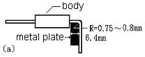
| 9.3.2 Torsional strength |
| Equipment: Torsion tester |
| Bend the terminal 6.4mm away from the body according to
Fig-a to 90 degree with a curvature of |
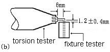
| 0.75mm~0.80mm. The lead wire should be clamped at a point
of 1.2mm away from the bending |
| point by a fixture which can rotate 360 degree according
to Fig-b. Rotate the resistor 360 degree |
| clockwise and counter clockwise for 1 cycle. The rotation
speed is 360 degree per 5 sec.. Perform |
| 3 cycles for the lead wire diameter of 0.8φ and 1.5 cycles
for that of 0.6φ. The terminal should not |
| break down or detached from the body. The acceptable change
of resistance is ±(0.5%+0.05Ω). |
  |
| |