| 1. Scope of the coverage: |
| This specification is pertinent to the application of insulated
0Ω resistors (designated as RZ). |
| 2 .Temperature range of the application: |
| -55℃ ~ +155℃。 |
| 3. Type: |
| The color of the coating resin for the 0Ω insulated
resistors is gray. |
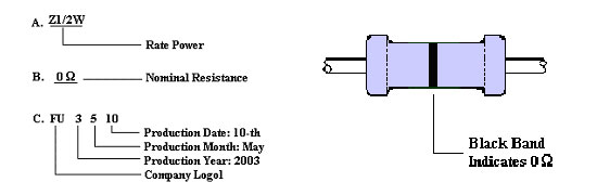
| 4.Marking and illustration: |
| Two types of designation methods are available for 0Ωinsulated
resistors. One is black ink |
| alphanumeric marking and the other one is color code marking.
The criteria of using either one of |
| the marking methods depend on the size of the resistors
and customers request which is listed in |
| the following: |
| alphanumeric marking ---->1/2W (Fig.1) |
| color code marking ------------>1/6W、1/4W (Fig.2) |
| |
 |
| |
| 5.Dimension, voltage, resistance range: listed in
the following Table-1 |
| Rated
power
(W) |
Type |
Resistance (Ω) |
 2 2 |
| J ( ±5%) |
L |
Dψ |
ι |
dψ |
| 1/6 |
Normal |
20mΩ以下 |
1.5A |
1.8±0.3 |
28±2 |
0.45±0.05 |
| 1/4 |
Normal |
20mΩ以下 |
2.5A |
2.4±0.1 |
28±2 |
0.60±0.05 |
| 1/2 |
Normal |
20mΩ以下 |
2.5A |
3.0±0.5 |
30±3 |
0.60±0.05 |
|
| |
| 6.Coating |
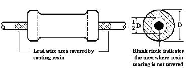 |
| 6.1 The body of the resistor is covered by nonflammable
silicon resin. |
| 6.2 The maximum length of the lead wire covered by the
resin is 2mm. |
| 6.3 The maximum area of the end cap which is not covered
by the resin is half of the diameter of |
| 6.3 the cap. |
| 6.4 The status of coating condition described by 6.2 and
6.3 are acceptable. |
| |
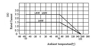
| 7.Characteristics of electrical performance |
| 7.1 Rated power |
| The rated power indicates the maximum power the resistor
can endure continuously when the |
| ambient temperature is equal to or lower than 70℃. When
the ambient temperature is higher than |
| 70℃, the rated power of the resistor is determined by the
derating curve described in the following |
| figure. |
 |
| 7.2 Dielectric strength (Ref. JIS C5202 5.7) |
| Equipment: Dielectric strength tester |
| The body of the resistor is wrapped around by the aluminum
foil without extending beyond the |
| resistor body. Clap one electrode on the aluminum foil
and the other electrode on the lead wire. |
| Apply following voltage from the tester to the resistor
for 1 min.. No flash-over, burning or |
| breakdown should be observed. |
| |
| Wattage |
1/6W |
1/4W |
1/2W |
| Voltage |
300V |
500V |
500V |
|
| |
| 8.Environmental tests |
| 8.1 Load life test (Endurance with rated load) (Ref. JIS
C5202 7.10) |
| Equipment: High temperature chamber and DC power supply |
| The resistors are put in a fixture where no interference
will be allowed. Put the fixture in a 70±3℃ |
chamber and apply rated current in table-1 with a cycle
of 90 min. ON and 30 min. OFF for 
|
| hours. After 240, 480, 720 and 1,000 hours, the resistors
are taken out and stabilize at room |
| temperature for 30 min. and then the resistance is measured.
Upon each step of resistance |
| measurement, the change of the resistance should be≦20mΩ
and the appearance should show |
| no remarkable abnormality and legibility of marking. |
| |
| 8.2 Endurance under damp heat and load (Ref. JIS C5202
7.9) |
| Equipment: Constant temperature and humidity chamber, DC
power supply |
| The resistors are put in a fixture where no interference
will be allowed. Put the fixture in a 40±2℃ |
| chamber with RH=90~95% and apply rated current in table-1
with a cycle of 90 min. ON and 30 |
| min. OFF for hours. Water drops should avoid
dripping on the resistors. After 240 and |
| 1,000 hours, the resistors are taken out and stabilize
at room temperature for 1 hour and then the |
| resistance is measured. Upon each step of measurement,
the change of the resistance should be |
| ≦20mΩ and the appearance should show no remarkable abnormality
and legibility of marking. |
| |
| 8.3 Temperature cycling (Ref. JIS C5202 7.4) |
| Equipment: High temperature chamber, low temperature chamber |
| Put the resistor to -55℃ chamber for 30 min. then take
it out at room temperature for 2 to 3 min.. |
| Put the resistor to +85℃ chamber for 30 min. then take
it out at room temperature for 2 to 3 min. |
| This completes a cycle. Repeat the cycle 5 times. Put resistors
at room temperature for 90 min. |
| and then measure the resistance. Compare the resistance
before and after test. The acceptable |
| change of resistance is≦20mΩ. The appearance should show
no remarkable abnormality and |
| legibility of marking. |
| |
| 9.Mechanical performance |
| 9.1 Resistance to soldering heat (Ref. JIS C5202 6.4) |
| Equipment: Solder bath |
| Measure the resistance before the test. Immerse part of
the lead wire which is 4±0.8mm away |
| from the body to the flux for 5 - 10 sec. Take the resistor
out and immerse resistors in the solder |
| bath of 350±10℃ for 3.5±0.5 sec.. Stabilize at room temperature
for 1 hour and then measure the |
| resistance value. Compare the resistance values before
and after the test, The acceptable change |
| is ≦20mΩ. |
| |
| 9.2 Solderability (Ref. JIS C5202 6.5) |
| Equipment: Solder bath |
| Immerse part of the lead wire which is 4±0.8mm away from
the body to the flux for 5 - 10 sec. Take |
| the resistor out and immerse resistors in the
solder bath of 245±5℃ for 3.5±0.5 sec. Take the |
| resistor out and inspect the lead wire visually. The acceptable
level is the coverage of the new |
| solder to be 95%. The composition of the solder bath is
99.7% tin and 0.3% Cu. |
| |
| 9.3 Robustness of terminals (Ref. JIS C5202 6.1) |
| 9.3.1 Tensile strength of termination |
| Equipment: Weight gauge |
| Fixed the resistor and apply axially along the lead wire
of 2.5Kg (0.8φ lead wire) , 1.0Kg (0.6φ lead |
| wire) or 0.5Kg (0.45φ lead wire) for 30 sec.. The lead
wire should not break or detached from the |
| resistor and the change of the resistance should be ≦20mΩ. |
| |
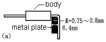
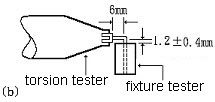
| 9.3.2 Torsional strength |
| Equipment: Torsion tester |
| Bend the terminal 6.4mm away from the body according to
Fig-a to 90 degree with a curvature of |
| 0.75mm~0.80mm. The lead wire should be clamped at a point
of 1.2mm away from the bending |
| point by a fixture which can rotate 360 degree according
to Fig-b. Rotate the resistor 360 degree |
| clockwise and counter clockwise for 1 cycle. The rotation
speed is 360 degree per 5 sec.. Perform |
| 3 cycles for the lead wire diameter of 0.8φ, 1.5 cycles
for that of 0.6φ or 1 cycle for 0.45φ. The |
| terminal should not break down or detached from the body.
The acceptable change of resistance |
| is ≦20mΩ. |
  |
| |